DIY One-Arm Bandit/Squeegee
August 28, 2010
This post doesn’t give ultra specific instructions down to what size hole to drill and what size bolts I used. Rather, it’s a million photos with a specific enough narrative voice to get you well on your way.
I broke the DIY engineering into three separate segments:
1) the arm and lateral movement mechanism
2) the squeegee holder
3) a device which would allow me to attach the squeegee holder to the arm in a way that allows for free side-to-side movement but prevents back-and-forth movement
Let’s go!
STEP 1 - ARM AND LATERAL MOVEMENT MECHANISM
I thought about DIY engineering this first part then realized an infinitely better solution could be purchased for $75:
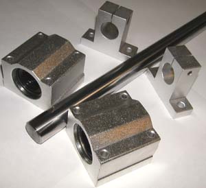
It’s a part that falls under the banner of “linear motion” mechanisms. I got mine through VXB (which, BTW, is such an appropriately obtuse name for a company that sells ball bearings). An eBay search of “linear motion” brings up any number of bar sizes, bearing configurations, and companies. It seems like these parts are currently marketed toward people building their own DIY CNC routers. Regardless, these sleds move right and left across the shaft as well as “around” it. Exactly what a one-arm bandit needs!
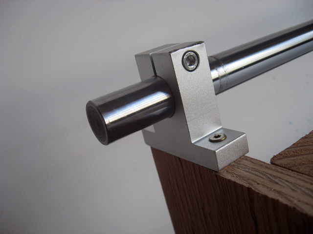
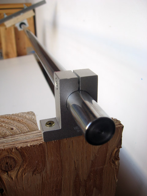
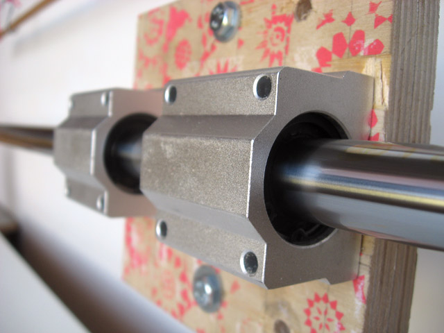
Here are the shaft and two supports
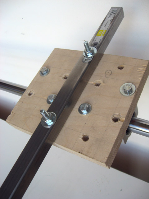
With the shaft mounted it’s time to deal with the bearing sleds. I attached the sleds to two layers of scrap 1/2” birch plywood with bolts. The four holes in each sled are tapped so I didn’t need to bolts all the way through: the bolt grabs onto the threads and pulls the shafts snug with the plywood.
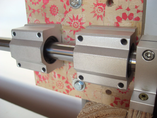
Discovery #1: hole drilling precision is pretty important for attaching the sleds to the plywood. If the sleds are slightly out of alignment in relation to the shaft there will be grinding when you try to move the sleds right and left. BE FOREWARNED!
The arm is then bolted to the plywood platform at a 90 degree angle in relation to the shaft.
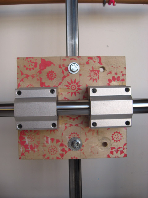
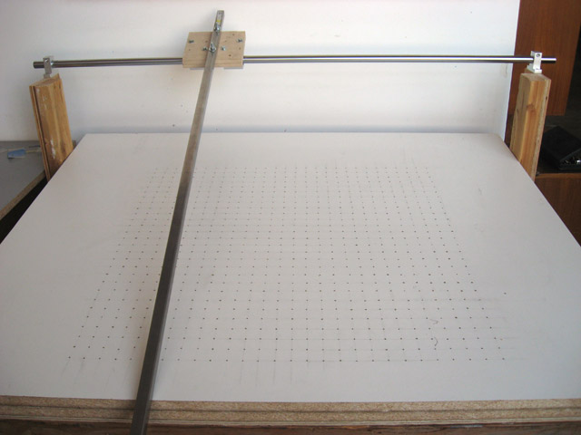
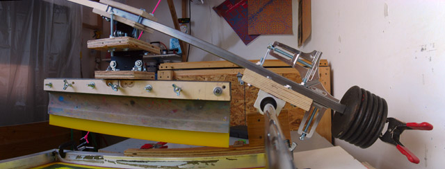
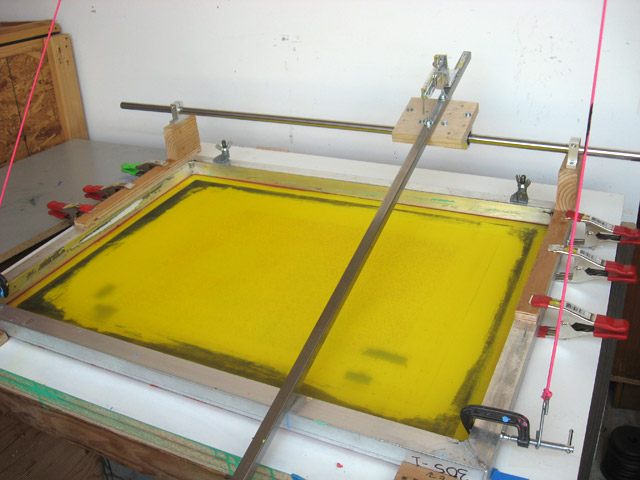
Here’s what we’ve built so far
So at this point we have an arm which moves right and left and up and down while maintaining a 90 degree relationship to the shaft. Cool!
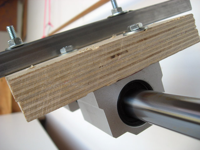
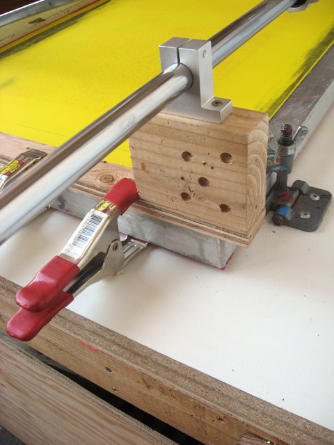
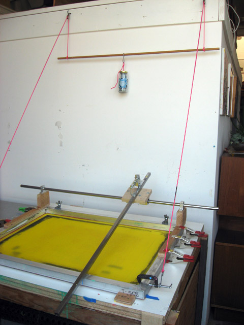
We now need to link the shaft and shaft supports with the up/down movement of the screen to ensure that the track of the squeegee falls along the same place on the screen regardless of screen’s “up or down-ness.” This is all to say I mounted everything onto the screen frame. The shaft supports were screwed into chunks of 2” x 4” which were screwed into strips of 3/4” plywood which were pony-clamped onto the screen
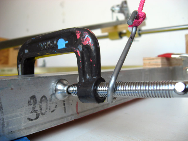
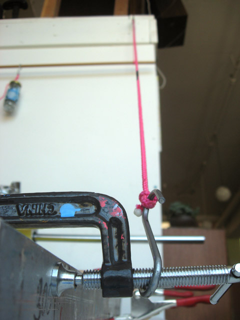
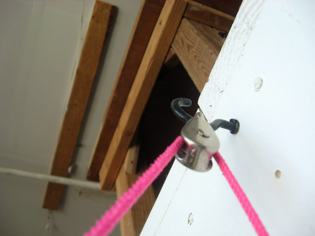
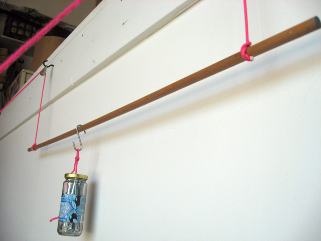
The screen counterbalancing system I’ve been using for a while is really simple
STEP 2 - SQUEEGEE HOLDER
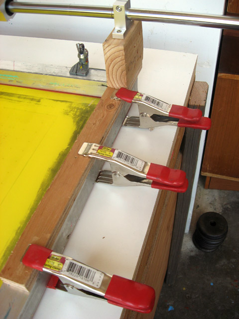
This is where some awesome DIY engineering starts. I found a piece of solid strut channel
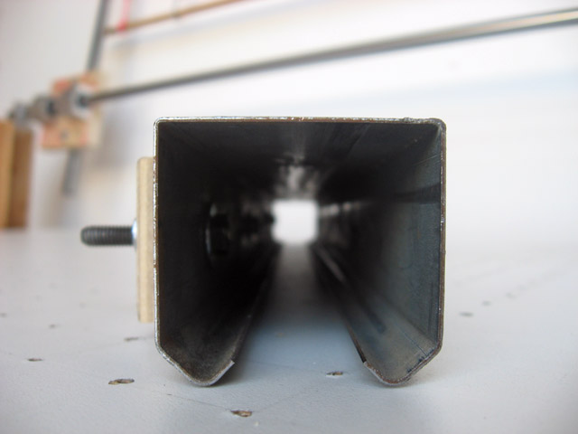
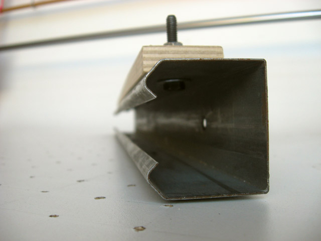
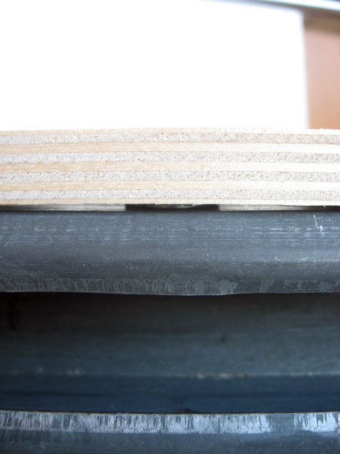
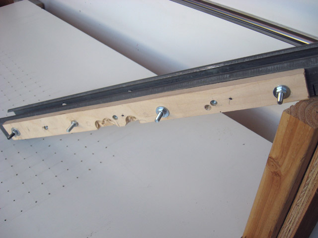
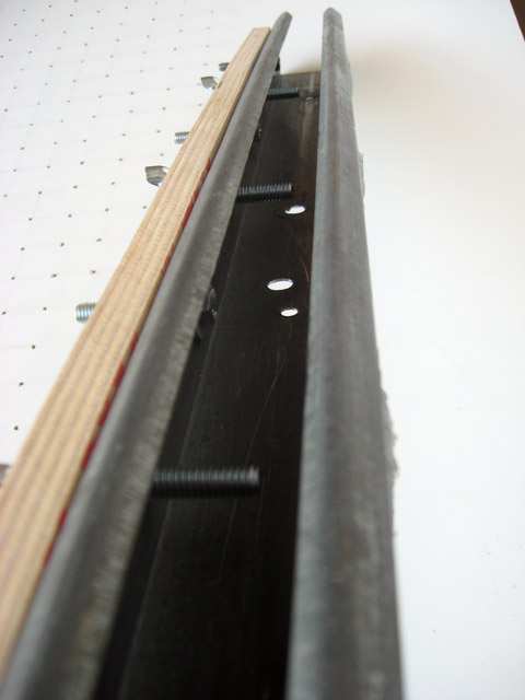
To this strut channel I affixed another piece of scrap 1/2” birch plywood which will act as a bolting mechanism to hold the squeegee in place.
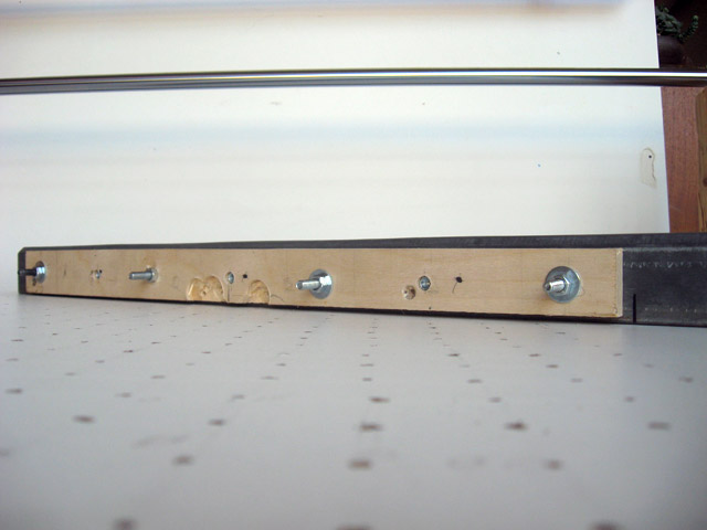
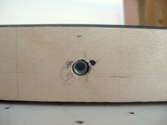
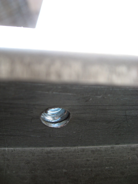
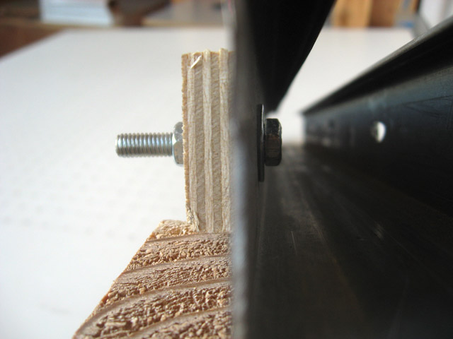
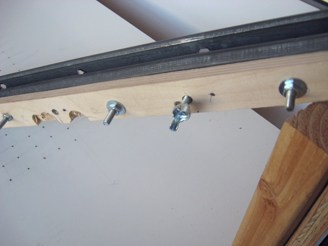
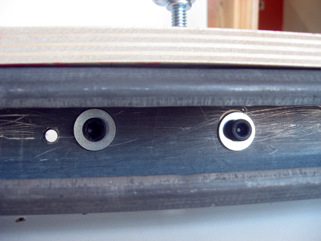
Between the four bolts in the above photo are three t-nuts. These t-nuts are pushed through the back of the plywood and provide threads for three clamping bolts. Later we’ll see how these bolts will hold the squeegee in place. Here are close-ups of the t-nut from the outside of the plywood, from between the plywood and strut channel, and finally from the inside of the strut channel
The plywood strip is held onto the strut channel with bolts
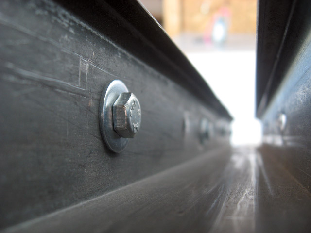
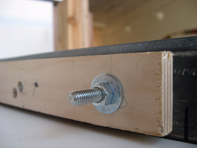
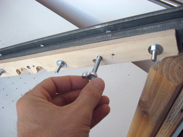
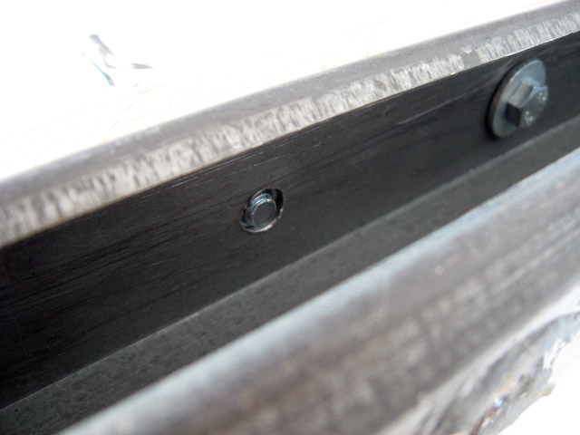
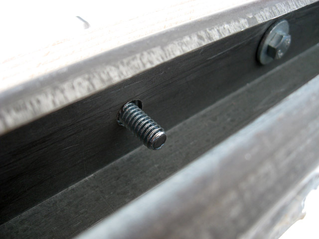
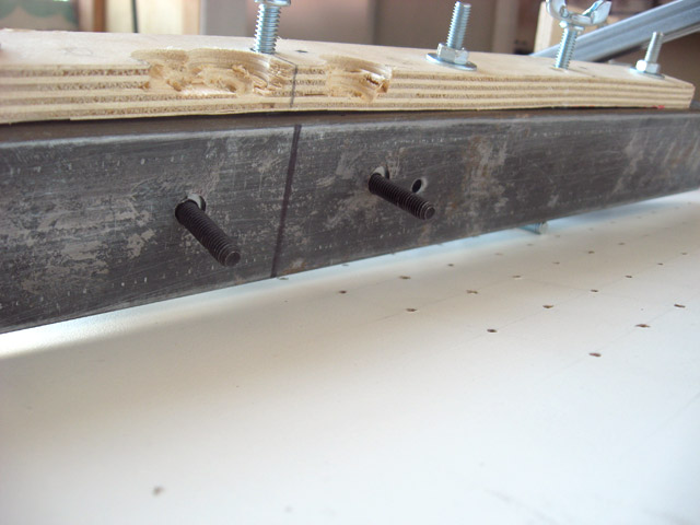
Here’s a series of photo showing the insertion of the clamping bolt from both the outside and inside of the strut
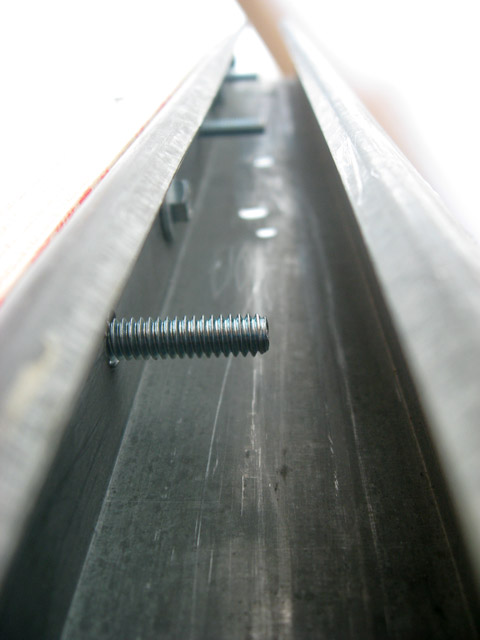
And here’s what it looks like on the inside of the strut with all three clamping bolts screwed in
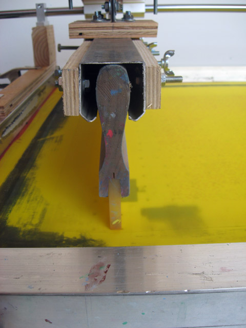
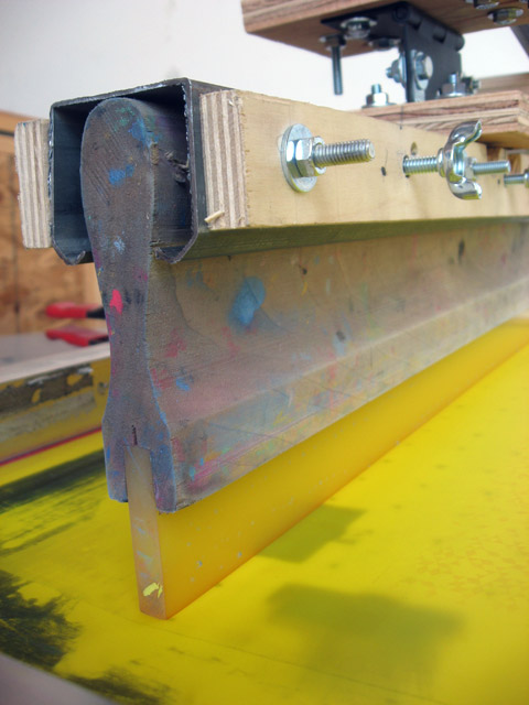
Now do all those previous steps onto the other site of the strut channel! Now we have a spolid squeegee holder. Slide the squeegee in and tighten all the bolts. (NOTE: I took photos a little out of order. The next two photos show things I haven’t explained yet. Don’t get confused!)
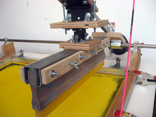
STEP 3 - SQUEEGEE HOLDER TO ARM
So now we have an arm that moves and a squeegee holder. We now need to interface the two. This probably was the most baffling part of the process for me. Then it turns out a very easy solution exists: door hinges!
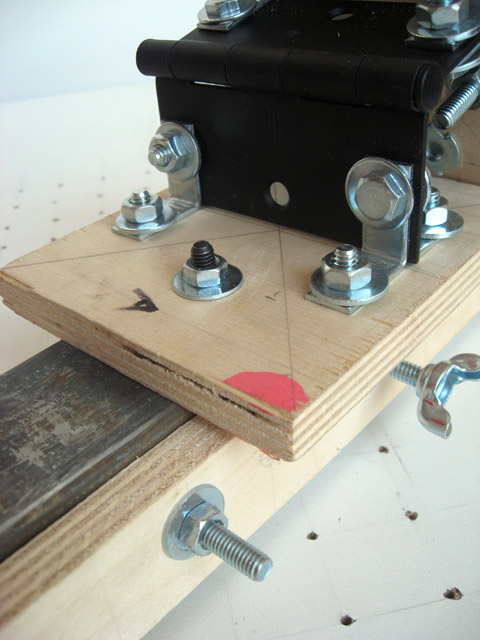
I took three more scraps of plywood, marked their centers, attached two sets of 3 1/2 inch door hinges at 90 degree angles of each other, and bolted this whole thing together. I also added limiter bolts
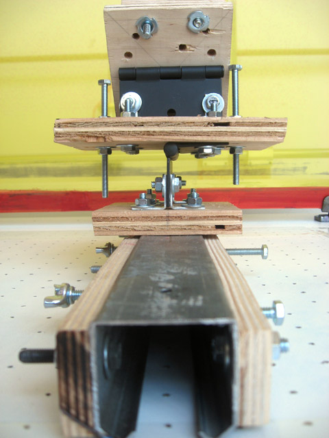
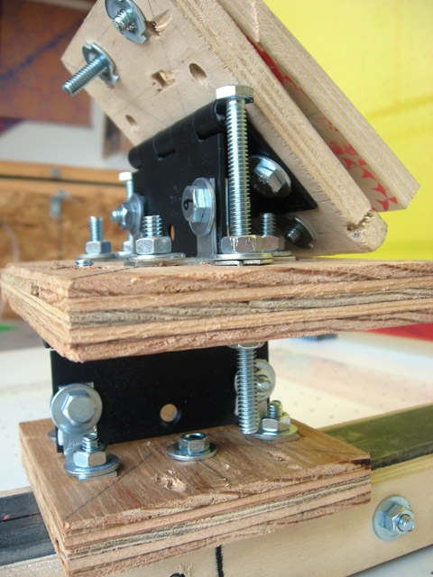
Attaching the squeegee holder was easily accomplished with more bolts with a caveat. Care is necessary in aligning the hinge with the center of the squeegee holder itself. This ensures the squeegee always hangs parallel with the ground. NOTE: I used allen bolts at this point because getting a wrench into the strut to hold the bolt whilst tightening the nut would have been really annoying.
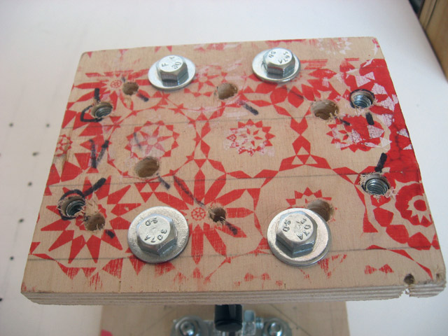
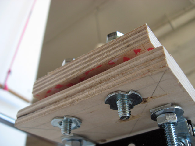
Here is a shot of the top piece of plywood (note: there’s a slew of extra holes in this top piece. SCRAP WOOD!). You can see the t-nut holes circled with a sharpie
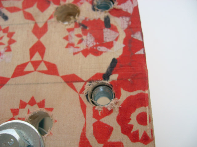
Here’s why we needed t-nuts in that top piece of plywood: Bolts are going through this new piece of plywood and screwing into the t-nuts. This will enable us to clamp this whole mechanism onto the arm we built in step one (NOTE: again, the next three photos were take before I added the second hinge. Pretend like there’s two!)
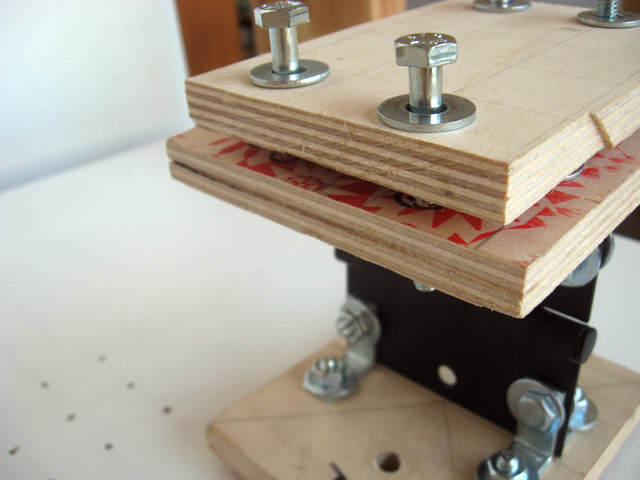
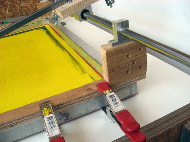
Here’s how this whole piece slides onto the arm
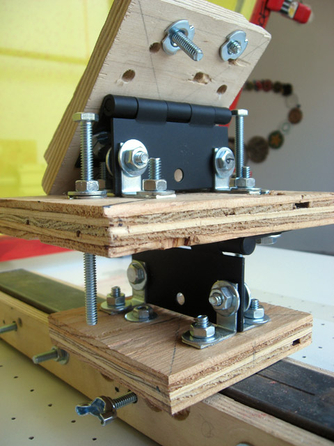
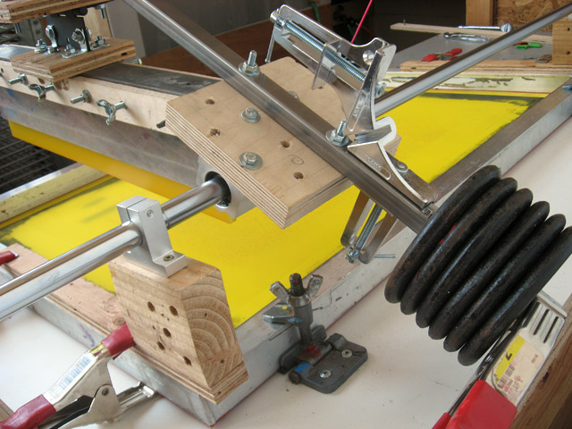
And here is everything fully attached
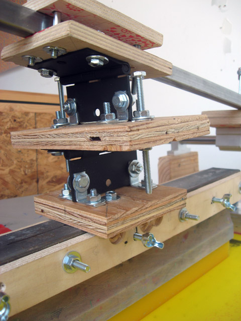
This two hinge set-up means the squeegee can pivot both “side-to-side” and “front-to-back”
So what’s up with these limiter bolts? Here’s how they work: the plate attached to the strut channel hits the end of the bold thus allowing me to set the maximum play in either direction
With the limiter bolts retracted the play of the print/flood adjustment is quite large
By having two directions of movement, the squeegee is able to “set” itself parallel to the printing surface, even if the printing surface isn’t parallel with the hanging squeegee (like mine)
You can see how the squeegee first hits the screen with only one edge. But as the bar is pulled across the table the squeegee “settles” into the screen and quickly gains full contact.
Finally I just added some used weight to the back of the squeegee arm for counterbalancing
Hooray! Completed! This project couldn't have happened without the help and input from the Gigposters community!